Description:
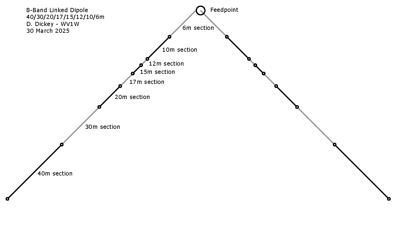
It is really simple once you learn how it is designed. This linked inverted V covers 8 bands, and you can make it with wire you might have on-hand. When done, the antenna can fit in your pocket or a plastic sandwich bag.
Advantages:
• excellent on-air performance
• no lossy transformer required = efficient
• ground-independent - no counterpoise required
• easy to build with commonly available materials
• very inexpensive (possibly no cost)
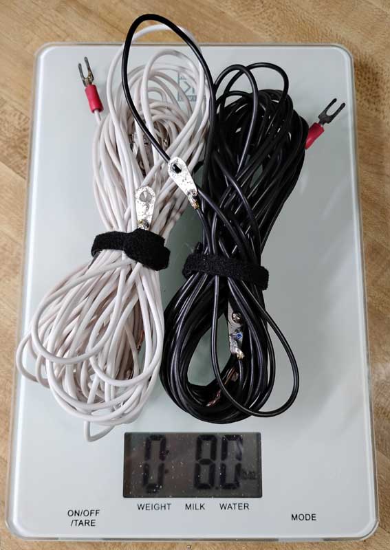
• compact & lightweight (8 oz)
One disadvantage is the requirement for a support. While a suitable tree limb could easily work in many parks, some operators will need a mast to deploy this antenna.
Theory:
The design is basically a half-wave dipole with very simple bolted joints between sections. With all segments bolted together you have a half-wave 40m dipole. By unbolting a pair of segments (one on each side) and using what’s left you can change bands as desired. It only takes a few minutes to lower the antenna, remove sections, and pull it back up.
It does NOT require a counterpoise system.
(click pictures to expand)
Construction:
The antenna should be approximately a half wavelength (½λ) long for each band. Use an online antenna calculator (or 234/MHz = length in feet) at the frequency you are designing for. I tuned mine for the middle of General class phone band segments except 10m for the Tech class phone segment and 30m for FT8.
To build the 8-band linked inverted V antenna, you need 62 feet of wire. Separated zip cord or speaker wire would be fine. I used 18-gage insulated stranded wire scavenged from a vacuum cleaner power cord found at the curb on trash night.
Calculated Lengths before tuning |
BAND |
FREQ-MHz |
LENGTH-FT |
LENGTH-IN |
SECTION-IN |
40M |
7.24 |
32.3 |
388 |
111 |
30M |
10.13 |
23.1 |
277 |
81 |
20M |
14.29 |
16.4 |
197 |
42 |
17M |
18.14 |
12.9 |
155 |
23 |
15M |
21.36 |
11.0 |
131 |
19 |
12M |
24.96 |
9.4 |
113 |
14 |
10M |
28.40 |
8.2 |
99 |
45 |
6M |
52.52 |
4.5 |
53 |
53 |
Actual Tuned Lengths |
BAND |
FREQ-MHz |
LENGTH-FT |
LENGTH-IN |
SECTION-IN |
40M |
7.24 |
31.1 |
373 |
106 |
30M |
10.13 |
22.2 |
267 |
78 |
20M |
14.29 |
15.7 |
189 |
40 |
17M |
18.14 |
12.4 |
149 |
22 |
15M |
21.36 |
10.5 |
126 |
18 |
12M |
24.96 |
9.0 |
108 |
13 |
10M |
28.40 |
7.9 |
95 |
44 |
6M |
52.52 |
4.3 |
51 |
51 |
|
|
|
 |
 |
 |
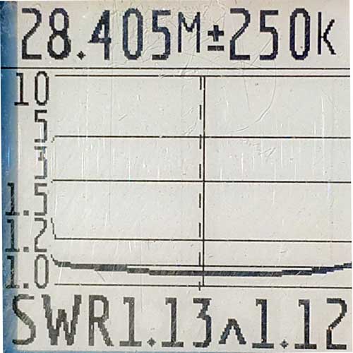 |
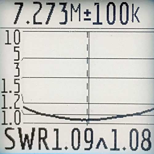
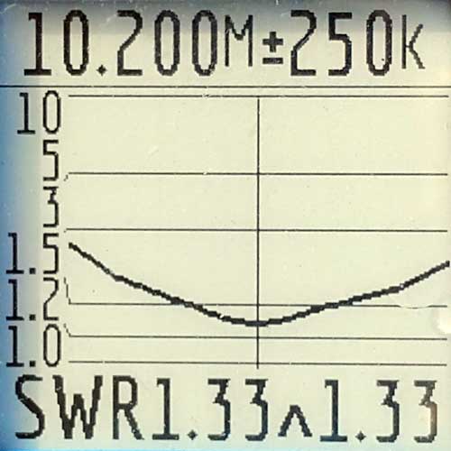
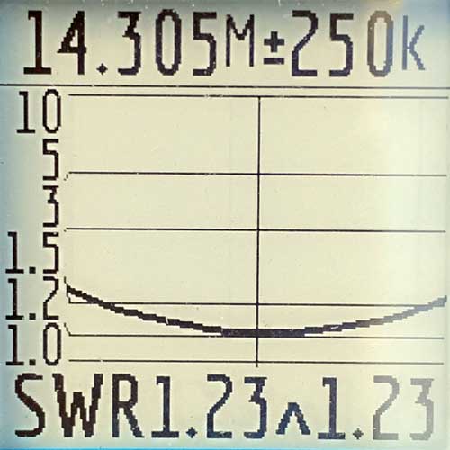
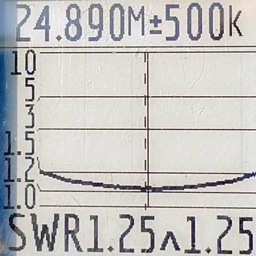
40m |
30m |
20m |
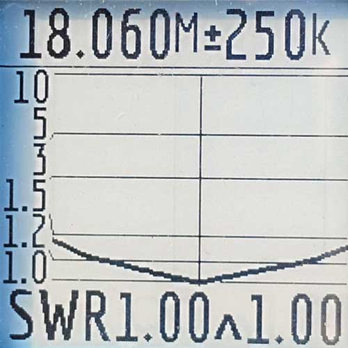
17m |
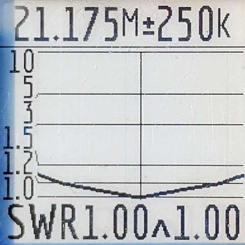
15m |
12m |
10m |
SWR can be adjusted by changing the apex angle of the V. A wider angle will have a lower resonant frequency. Raising the feedpoint without changing the end anchor positions will make the angle narrower and raise the resonant frequency.
You can tweak section lengths for best SWR if necessary. Of course, an analyzer will make tuning easy and precise, but you can use the SWR meter in your rig if you don’t have one.
Sections can be labeled with a permanent marker (Sharpie) using wide and narrow bands with wide = 10. As examples: 2 wide bands = 20m and 1 wide band plus 5 thin bands = 15m. You don't really need to label both sides because you can match the unlabeled sections to the labeled ones. With my black and white dipole, I only labeled the white sections.

Some operators can simplify their design by eliminating bands they don't use. Limiting the dipole to covering 20m through 10m would be an example of a useful 5-ban design.
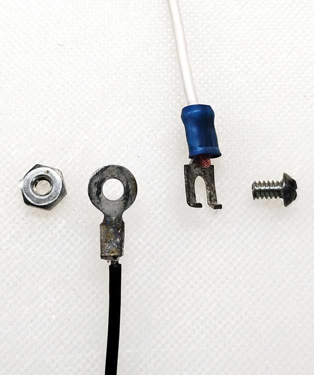
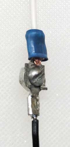
Sections are joined with a short machine screw (bolt) and nut. TIP: Use a small plastic "S-Biners" from Nite-Ize between antenna sections to "unlink" sections below and keep the overall length the same as you change bands.
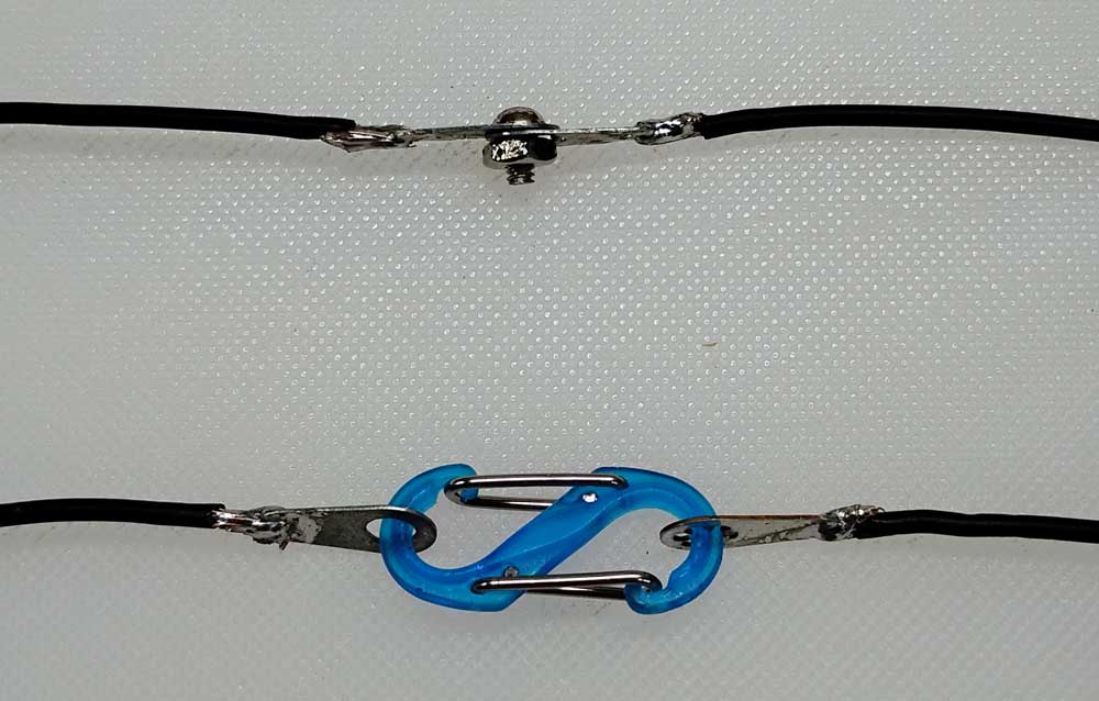
Optionally, you can use fork terminals at the top of each section to make band changes easier without having to completely disassemble the hardware. Just loosen the screw a few turns and slip the fork out. Choose fork terminals with tips bent to prevent them from slipping out from under the screw head until it's loosened several turns.
After use, I wrap the wire around thumb and pinky fingers in a figure-8 for storage. This prevents adding a twist to the wire. |